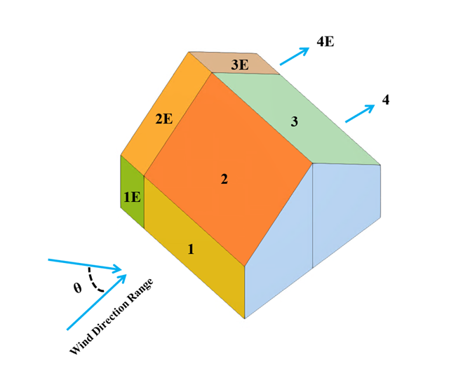
Im aktuellen Validierungsbeispiel wird der Winddruckbeiwert (Cp) sowohl für Hauptbauteile (Cp,ave ) als auch für Nebenbauteile wie Verkleidungen oder Fassadensysteme (Cp,lokal ) basierend auf NBC 2020 Siehe [1] and Japanische Windkanal-Datenbank für niedrige Gebäude mit einer Neigung von 45 Grad. Die empfohlene Einstellung für ein dreidimensionales Flachdach mit spitz zulaufender Traufe wird im nächsten Teil beschrieben.
Es ist nachzuweisen, dass ein Träger mit unterschiedlichen Querschnitten aus der Legierung 6061-T6 für die erforderliche Last gemäß dem Aluminum Design Manual 2020 geeignet ist.
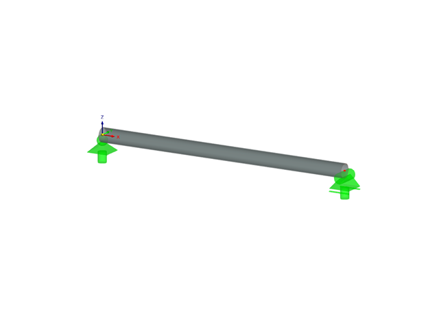
Es ist die zulässige Normaldruckfestigkeit eines gelenkigen, aus der Legierung 6061-T6 hergestellten 2,44 m langen Trägers mit verschiedenen Querschnitten zu ermitteln, der seitlich eingespannt ist, um das Knicken um seine schwache Achse gemäß ADM (Aluminum Design Manual) zu vermeiden.
Es ist die zulässige Normaldruckfestigkeit eines gelenkigen, aus der Legierung 6061-T6 hergestellten 2,44 m langen Trägers mit verschiedenen Querschnitten zu ermitteln, der seitlich eingespannt ist, um das Knicken um seine schwache Achse gemäß ADM (Aluminum Design Manual) zu vermeiden.
Es ist nachzuweisen, dass ein Träger mit unterschiedlichen Querschnitten aus der Legierung 6061-T6 für die erforderliche Last gemäß dem Aluminum Design Manual 2020 geeignet ist.
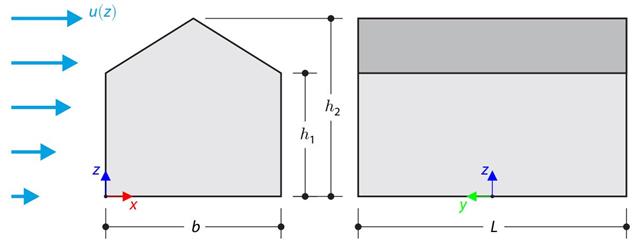
Im Verifikationsbeispiel wird die Windlastberechnung an einem Gebäude mit Satteldach unter Verwendung der Norm EN 1991-1-4 mit der CFD-Simulation in RWIND Simulation verglichen. The building is defined according to the sketch, and the inflow velocity profile is taken according to the standard EN 1991-1-4.
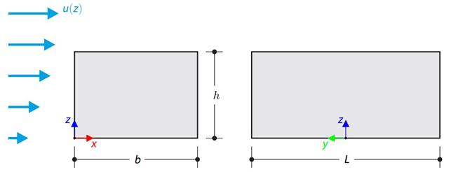
Im Verifikationsbeispiel wird die Windlastberechnung an einem Flachdachgebäude unter Verwendung der Norm EN 1991-1-4 mit der CFD-Simulation aus RWIND Simulation verglichen. The building is defined according to the sketch, and the inflow velocity profile is taken according to the standard EN 1991-1-4.
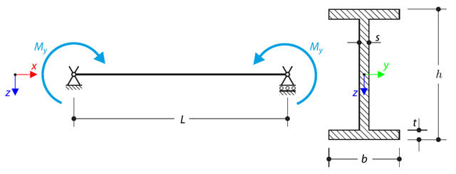
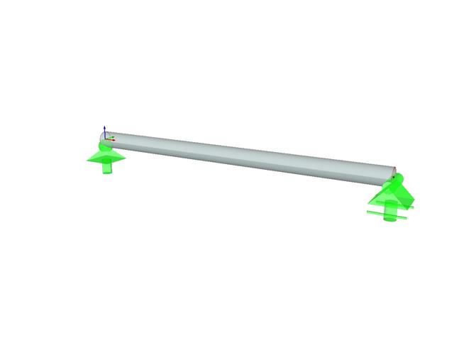
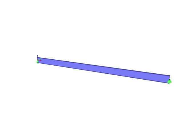
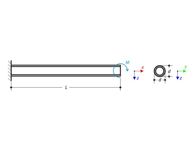
A simply supported beam is loaded by pure bending. Aufgrund des Biegeknickens versuchen Sie die Verzweigungslast und den zugehörigen Lastfaktor zu ermitteln.
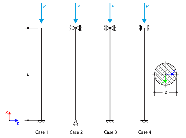
A strut with a circular cross-section is supported according to four basic cases of Euler buckling and subjected to pressure force. Ermitteln Sie die Verzweigungslast.
Berücksichtigen Sie die im Bild Nr.1 dargestellte Stabspannweite ASTM A992 W 18 × 50 und die gleichmäßigen Eigen- und Nutzlasten. The member is limited to a maximum nominal depth of 18 inches. The live load deflection is limited to L/360. The beam is simply supported and continuously braced. Verify the available flexural strength of the selected beam, based on LRFD and ASD.
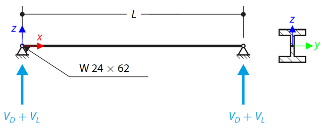
Ein Träger vom Typ ASTM A992 W 24×62 mit Endscherkräften von Eigen- und Nutzlast i.H.v. 48.000 und 145.000 kips ist in Bild 1 dargestellt. Verify the available shear strength of the selected beam, based on LRFD and ASD.
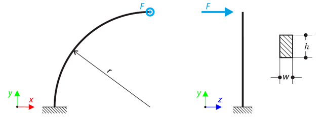
Ein Viertelkreisstab mit rechteckigem Querschnitt wird mit einer außerhalb der Ebene befindlichen Kraft belastet. This force causes a bending moment, torsional moment, and transverse force. While neglecting self-weight, determine the total deflection of the curved beam.
Ein gekrümmter Träger besteht aus zwei Trägern mit rechteckigem Querschnitt. The horizontal beam is loaded by distributed loading. While neglecting self-weight, determine the maximum stress on the top surface of the horizontal beam.
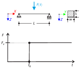
In der Mitte der Spannweite eines einfach gelagerten Trägers wird zu einem bestimmten Zeitpunkt eine konzentrierte Kraft aufgebracht. Considering only the small deformation theory, determine the maximum deflection of the beam.
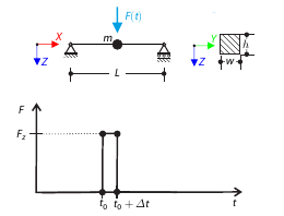
Eine konzentrierte Kraft wird für kurze Zeit in der Mitte eines einfach gelagerten Trägers angewendet. Considering only the small deformation theory and assuming that the mass of the beam is concentrated at its mid‑span, determine its maximum deflection.
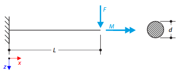
Ein Kragarm mit einem kreisförmigen Querschnitt wird durch konzentrierte Biege- und Drehkraft belastet. The aim of this verification example is to compare the reduced stress according to the von Mises and Tresca theories.
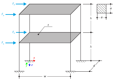
Dieses Beispiel dient zur Veranschaulichung der Ebene. The application is shown on a two-story structure. The structure is loaded by means of lateral forces according to Figure 1. Determine the maximum deflection of the structure ux in the direction of the loading forces using both the diaphragm constraint and the plate model of the floor.
A cantilever is loaded by a moment at its free end. Using the geometrically linear analysis and large deformation analysis, and neglecting the beam's self-weight, determine the maximum deflections at the free end. Dieses Verifikationsbeispiel basiert auf dem von Gensichen und Lumpe vorgestellten Beispiel.
A member with the given boundary conditions is loaded by torsional moment and axial force. Neglecting its self-weight, determine the beam's maximum torsional deformation as well as its inner torsional moment, defined as the sum of a primary torsional moment and torsional moment caused by the normal force. Vergleichen Sie diese Werte, während Sie den Einfluss der Normalkraft annehmen oder nicht berücksichtigen. The verification example is based on the example introduced by Gensichen and Lumpe.
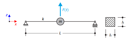
A long, thin beam is carrying a concentrated mass and is loaded by a time-dependent force. Er wird einfach gelagert. The problem is described using the following parameters. Determine the deflections in the given test times.
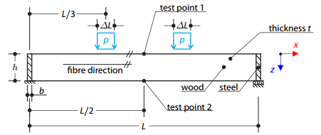
A timber beam reinforced by two steel plates at the ends is loaded by pressure. The wood fibers are parallel to the upper loaded side of the beam. Die plastische Oberfläche wird nach der Tsai-Wu-Plastizitätstheorie beschrieben.
Bestimmen Sie das Biegemoment, welches den Stab am freien Ende des Kragarms in eine kreisförmige Form biegt. Neglecting the beam's self-weight, assuming the large deformation analysis, and loading the cantilever with the moment, determine its maximum deflections.
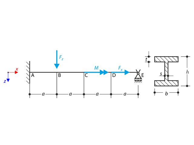
A beam is fully fixed (warping is restricted) on the left end and supported by a fork support (warping is enabled) on the right end. The beam is subjected to a torque, longitudinal force, and transverse force. Determine the behavior of the primary torsional moment, secondary torsional moment, and warping moment. Dieses Verifikationsbeispiel basiert auf dem von Gensichen und Lumpe vorgestellten Beispiel.
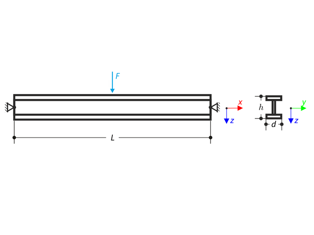
Ein an beiden Enden gelenkig gelagerter Träger wird in seiner Mitte mit konzentrierter Kraft belastet. Neglecting its self-weight and shear stiffness, determine the beam's maximum deflection, normal force, and moment at the mid-span, assuming the second- and third-order analysis.
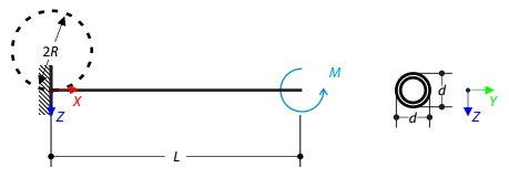
Stellen wir uns ein biegesteifes Gerüstrohr vor, das durch einen Knotenlager für Gerüst unten befestigt und sowohl durch ein Moment als auch durch eine Kraft belastet wird. Self-weight is not considered. Considering an infinitely rigid beam, determine the maximum radial deflection.
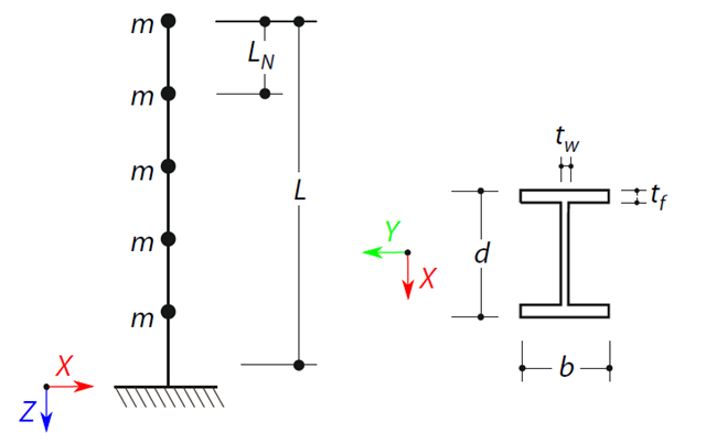
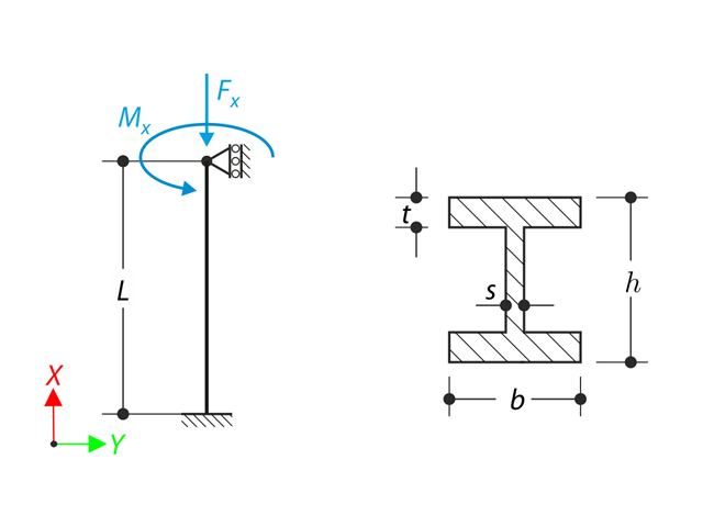
Es wird ein Kragträger mit einem I-Trägerquerschnitt der Länge L definiert. The beam has five mass points with masses m acting in the X-direction. The self-weight is neglected. The frequencies, mode shapes, and equivalent loads of this 5-DOF system are analytically calculated and compared with the results from RSTAB and RFEM.
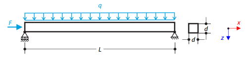
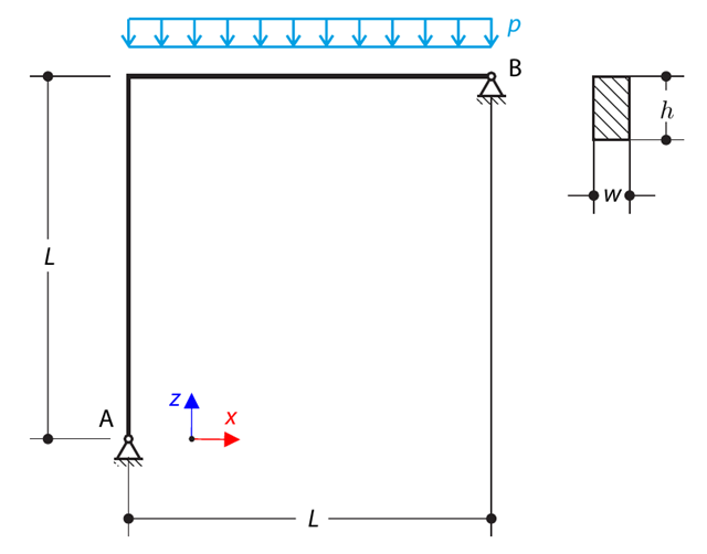
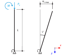
Ein Stahlträger mit quadratischem Querschnitt wird mit einer Normalkraft und einer verteilten Belastung beansprucht. The image shows the calculation of the maximum bending deflection and critical load factor according to the second-order analysis.
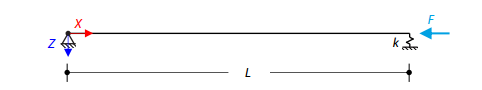
Ein axial belasteter Stahlträger mit quadratischem Querschnitt ist an einem Ende gelenkig gelagert und am anderen Ende federnd gelagert. Two cases with different spring stiffnesses are considered. The verification example solves the calculation of the load factors of the beam in the image using the linear stability analysis.
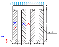
Bestimmen Sie die maximale Durchbiegung von vier unten befestigten Stützen, die oben durch einen starren Block verbunden sind. The block is loaded by pressure and modeled by an elastic material with a high modulus of elasticity. The outer columns are modeled as orthotropic elastic material, and the inner columns as orthotropic elastic-plastic material with the same elastic parameters as the outer columns and plasticity properties defined according to the Tsai-Wu plasticity theory.
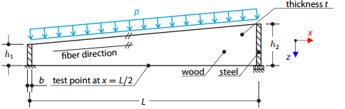
A timber beam reinforced by two steel plates at the ends is loaded by pressure. The wood fibers are parallel to the upper loaded side of the beam. Die plastische Oberfläche wird nach der Tsai-Wu-Plastizitätstheorie beschrieben.